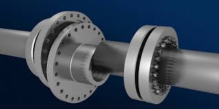
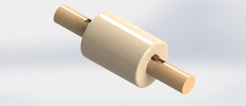
Coupling in the machine industry is interpreted as “a part that connects two shafts together”, and is generally called “coupling”, “shaft coupling” or “joint”. Power can be transmitted by using a coupling, even between axes of different diameters as shown in the following figures. The role of a coupling (shaft fitting).
Types of Couplings
There are many different sizes and shapes for couplings. While some of them are specially created for incredibly specialized conditions, others perform fine for generic applications.
Understanding the features and variations of the various types of couplings can help you make an educated decision. The following coupling types and how they operate are covered in this section:
- Rigid coupling
- Flexible coupling
- Sleeve or muff coupling
- Split muff coupling
- Flange coupling
- Beam coupling
- Fluid coupling
Rigid coupling
A stiff coupling, as its name implies, allows little or no relative movement between the shafts. Rigid couplings are preferred by engineers when exact alignment is required.
Rigid coupling is an umbrella term that encompasses several specialized couplings. It refers to any shaft coupling that can prevent any undesirable shaft movement. Sleeve, compression, and flange coupling are a few examples of this sort of shaft connection.

Flexible coupling
A flexible coupling is any shaft connection that can offer vibration isolation while allowing some degree of relative motion between the component shafts. A flexible coupling wouldn’t be necessary if shaft alignment was excellent all the time and there was no movement or vibration occurring when the machines were in use.

Sleeve or muff coupling
The simplest type of stiff style connection is a sleeve coupling. It is made up of a cast-iron muff or sleeve (hollow cylinder). Its internal diameter is the same as the coupled shafts’ outward diameter. To limit relative motion and avoid slippage between the shafts and the sleeves, a gib head key is used.

Split muff coupling
The sleeve in a sleeve coupling can be split into two pieces for simpler assembly. This eliminates the need for the technician to move the linked shafts during the construction or disassembly of a connection.

Flange coupling
A flange is slid onto each of the shafts to be linked in flange couplings. The flanges are fastened to one another by studs or bolts, and a key is used to connect them to the shaft. The flange hub can’t slide backward and expose the shaft interfaces, thus set screws or a tapered key are used to prevent this.

Beam coupling
A machined connection called a beam coupling has a great degree of flexibility for parallel, axial, and angular misalignment. One of the top low-power transmission couplings is this one

Fluid coupling
The impeller accelerates the fluid as the drive shaft turns, bringing it into contact with the runner blades. After giving the runner its mechanical energy, the fluid exits the blades at a slow speed.


